Rear Disc Installation Instructions Drum to Disc
The car in the pictures is a Factory Five Kit but everything came from a FOX body mustang. Our work is on a lift, this shows virtually every step.
×
- Place vehicle securely on jack stands prior to starting disassembly.
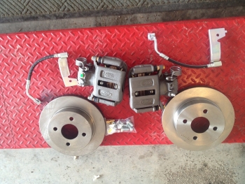
- Remove all items from package. Content varies by part number but basically 2 brackets 4 big bolts to mount caliper to bracket 2 fittings to convert hard to soft line and six small bolts for optional dust shield. Do not paint parts until test fit.
 Click images to enlarge
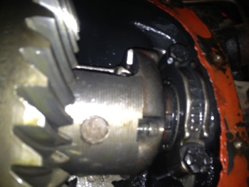
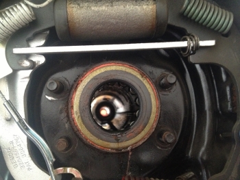
- Remove cover in the center of rear end and catch the gear oil. If fluid is old, replace with new and add new friction modifier after all steps below are finished.
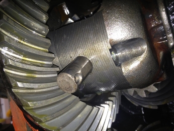
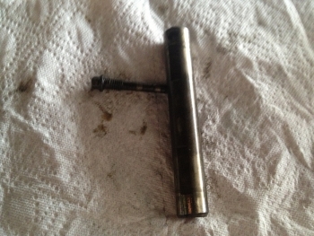
- Once cover is off, remove the 5/16” bolt that holds the big pin in the center of the traction lock unit. Remove pin once free. These are loc tite in so we find using a propane torch to heat the area between the pin and the bolt helps to release the loc tite.
- Remove wheels and brake drums on both sides.
- Remove brake lines from rear of wheel cylinder on both sides.
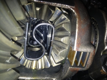
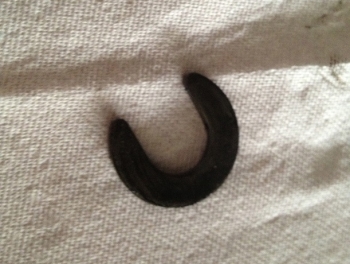
- Tap axles in to expose the C clips in the center of rear end. The big pin held the axles, so this is where the C clips will be. Remove C clips on each side, if worn-replace clips. Once C clips are out/off, the axles should slide out.
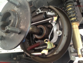
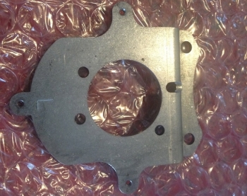
- The four bolts hidden by the axle and drum hold the brake backing plates on. Remove them from both sides and keep the bolts (backing plates are not re-used). Bolts are reused.
- The e brake cables need to come off the T cable above the exhaust and the drive shaft. It is a pain but not hard. We found a 12 point 13 MM socket will compress the clips on the cables where they go through the body mount. Put the socket over the small portion and push it to the chassis mount and twist the socket and cable while pushing first and then pulling on the cable. Or all the tabs will be broken and it will be even harder.
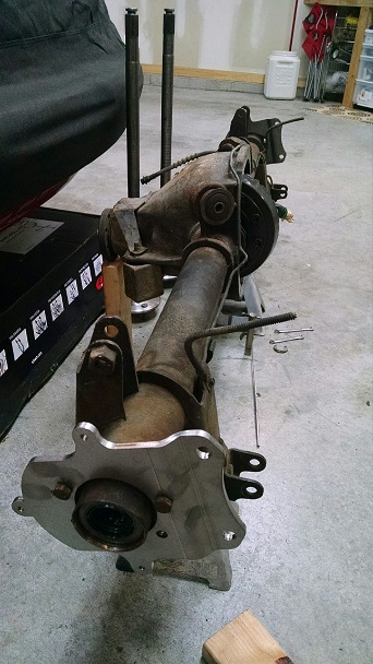
- Remove all of the old brake parts as one unit, repeat on the other side.
- The e brake cables need to come off the T cable above the exhaust and the drive shaft. It is a pain but not hard. We found a 12 point 13 MM socket will compress the clips on the cables where they go through the body mount. Put the socket over the small portion of the cable and push it to the chassis mount and twist the socket and cable while pushing first and then pulling on the cable. Or all the tabs will be broken and it will be even harder.
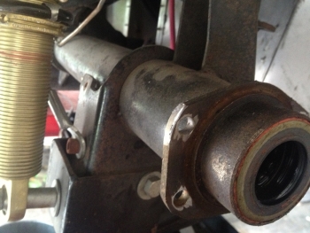
- Your new brackets mount where the backing plates used to be. Mount the brackets so the top tilts inboard and to the rear of the car re-using the bolts from step 7. There is a left and right-they may appear to be the same, but are not. For 4-lug and SN95 (see the pic below) the housings are not perfect and it may or may not be necessary to remove a VERY small amount of material from the casting that is on the end of the housing. We tried to rotate the parts to avoid this but there is too much in the way, bump stops and shocks to mention a few. Put the bracket on with the caliper ears inboard to the rear and rotate until the bolts line up. Grind if needed, Put bracket on again and if needed grind a little more. It takes very little to make them fit and many find no grinding is needed. Now you can paint the parts. For the Cobra brackets there is no need to grind the housing.
- PUT ‘C’ CLIPS ON AND PUSH AXLE BACK OUT TO IT’S NORMAL POSITION. THIS MUST BE DONE, NOT MATTER HOW CAREFULLY DONE THERE IS NO WAY TO CHECK ALIGNMENT WITHOUT THE PIN IN. THE LITTLE BOLT CAN WAIT BUT THE PIN AND C CLIP MUST BE IN.
- Mount rotors and caliper pad bracket. Remove the caliper and pads so all that is there is the support bracket. Thread sealer (Loc-tite) is recommended.
The order is:- bolt
- bracket
- washer (supplied spacer)
- caliper support (pad bracket)
- caliper
We over offset inboard to accommodate different axles, gears and differentials, we find it much easier to remover or add a washer than try to remove material perfectly flat.
Check for fit. It is close, but as long at there is a 1/16” space, it is fine. Remember to get C clips and cross pin on before checking calipers and rotors for fit. The optional dust shields can be mounted on the inside or outside of the bracket at this time. If mounted from outside, rotor will have to be removed to mount. In ten years we have never installed them.
This pic exaggerates the closeness but you get the idea. Center the bracket over the rotor. If it takes two washers fine, if not that is fine also. If it takes more than two washers (C clip eliminators) get a hardened washer the thickness of as many washers as used. For example if using three 1/16 washers get a 3/16 shim from the hardware store.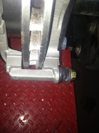
- Mount the pads, clips and caliper now that everything is centered. If the calipers and pads are too tight DO NOT compress the piston they have to be turned in. The parts store has the tool or a pair of needle nose pliers can do it push and turn at the same time.
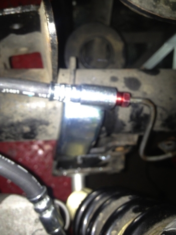
- Remove the clip that holds the hard line. Put the flex line in place on the top of the lower control arm mount. It fits really well in one spot and will line the soft brake hose with the caliper well. The hard line will need to be cut, bent or relocated to line up. There are two ways to mount it. One is reuse the old hole and bolt and flatten the tab on the end. OR use (drill) two holes one for the mounting hole and one for the alignment tab. If the line clamps have the screws in them, you can use them or get another to keep the lines fixed in their original location. We have found that relocating the lines works the best, so using the old screws in the new holes works fine. Sorry for the fuzzy pic but you get the idea.
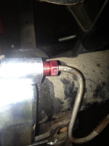
- Use the supplied fitting and cut, bend and double flare the hard line to go from the old drums to the newly mounted soft line. The hard line will be cut several inches in order to fit. Don’t forget to put the fitting on before you flare the line. (If this sounds like the voice of experience, it is)! There are several companies that offer pre made lines so no cutting and flaring is needed. Most auto parts stores rent the tool. We have done hundreds, practice on the cut off part and DO NOT over tighten the second part of the flare.
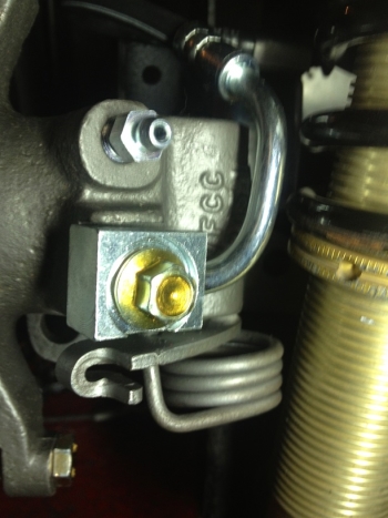
- Make sure there is a crush washer on both sides of the brake line. If using non OE lines (braided etc) make sure the banjo bolt does not bottom out before the washer crush. Generally the aftermarket ends are not as thick as the stock ones and shortening the bolt is common.
- This concludes the part of the install with North Racecars parts. These are the parts we have found you must have to complete the process. An M-2450-A plug to disable the proportioning valve. This must be done or the rear brakes will never get enough pressure.
- These parts are optional but highly recommended. A 93 cobra Master Cylinder (MC) and Booster. The stock 87 to 93 MC will work, just not well, it does not have enough volume. The booster helps with the extra pressure needed to put the larger MC. A 3 to 2 conversion makes the MC install pretty easy. Late Model Restoration has most of these items if not all. The MC and booster should be available locally 93 cobra NOT cobra R.
- Make sure all the connections to the brake system are tight. Bleed brakes, reinstall traction lock pin, bolt and cover. Fill with fluid, reinstall wheels, remove vehicle from jack stands and test brakes in a safe area. The fluid and brakes must work before the e brake install. Testing can be done after the cables but everything must be bled.
- E brake cables come with the complete kit. Here is the install process:
- Starting at the rear, put the lug through the hole in the caliper and put it the lever on the caliper. The sleeve will fall out of the caliper easily for now. Once there is tension it will be fine.
- The groove is for an e clip but that was only used to hold the cable in place on the assembly line. The outer of the cable will rub a wide tire. Ford had a bracket that attached to the lower control arm, we just cable (zip) tie it to the control arm with some old heater or fuel hose to protect it.
- Route the cables in the same position as the old cables. Before attaching them to the T cable, disable the spring in the handle. The handle has a bunch of stuff going on. On the left of the handle is the old self-adjuster and then the spring. Unwind that spring first — just pop it up and over.
- With the handle down put the new cables in the T cable under the car. Pull the handle to the first click and then push the T cable until it clicks in the self-adjuster.
- Now pull the handle up and see if the e brake works. Pull hard if it does and take a break. This will take the stretch out of the cables.
- After the break, put the handle down and rotate the wheel. If there is no resistance fine.
- We then pin the handle. There is a hole on the passenger side of the handle and we drill it bigger and drill a hole in the pull part of the handle so that when the handle is down there is no tension on the cables.
- IT IS VERY IMPORTANT THAT THE SPRING ON THE HANDLE DOES NOT PUT ANY PRESSURE ON THE CALIPER SPRINGS OR THE BRAKES WILL DRAG.